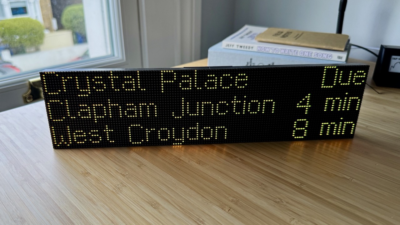
Arrivals is a Kotlin Multiplatform project for real-time public transit info. The most recent exploration was a Raspberry Pi driving an LCD. Now I’m going for character: a 128x32 dot-matrix board built from two chained LED panels, which feels like a miniature of the real thing.
If you’re interested in building this project, the README is comprehensive, so this post will cover the overall approach and gotchas.
Kotlin/Python bridge
Python is the standard language for talking to hardware via the Raspberry Pi’s GPIO headers. We need a way to connect the Kotlin app to Python LED display drivers.
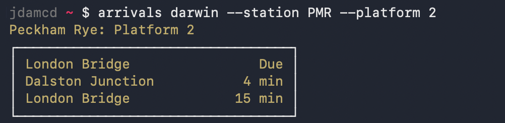
Luckily I’d already built a CLI target, so the approach was:
- Add a
--jsonoutput flag to the CLI - Build Kotlin/Native CLI artifacts to run with no JVM overhead on the Raspberry Pi Zero 2’s 512MB of RAM
- Call the CLI from a Python rendering script and parse the train times JSON
The Kotlin Multiplatform compiler doesn’t run on the Raspberry Pi’s linuxArm64 architecture, but the CLI binary can be cross-compiled from macOS or Linux x86 via the :cli:linkReleaseExecutableLinuxArm64 Gradle task.
Bitmap fonts
The LED matrix is a tiny 128x32 resolution, so we need a bitmap font where every pixel is fully on or off with no anti-aliasing. I tried out some public domain bitmap fonts to get a first version working. It looked… extremely disappointing.

The London Underground LED signs I’d hoped to emulate have some very distinctive elements:
- Capital letters are larger and sit one pixel below the baseline
iis a single columnyhas an odd horizontal descender, which you can see in the photo at the top of this post
Most generic bitmap fonts are monospaced (e.g. in 8x10.bdf every character is exactly 8 pixels wide and 10 pixels tall), so as well as not looking quite right for this project, they burn very limited horizontal space.
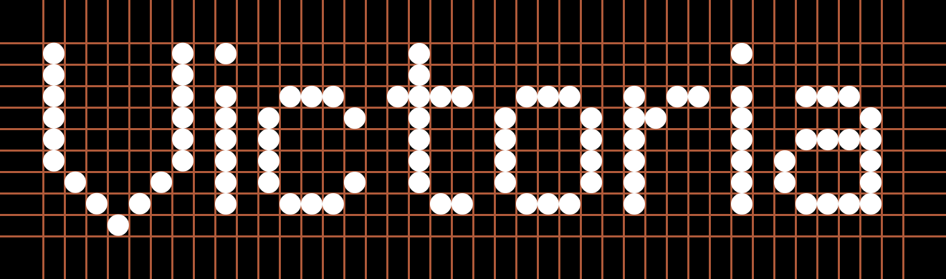

I used Claude Code to transcode a scalable TrueType reproduction of the London Underground dot matrix font into BDF – a 38-year-old format. The resulting bitmap font has a fixed height of 9 pixels and variable character width. That means we can squeeze in 3 rows with a panel height of 32 LEDs.
Flicker
Once everything was up and running, I noticed a subtle flicker whenever data was fetched, due to the Linux scheduler preempting the LED refresh thread. The fix was to reserve a core: adding isolcpus=3 to /boot/firmware/cmdline.txt keeps core 3 off-limits so the LED driver runs there exclusively. On the Pi Zero 2, the rgbmatrix library picks this up automatically; on the Pi 5, I’m running a patched Piomatter branch that pins the blit thread to the isolated core.
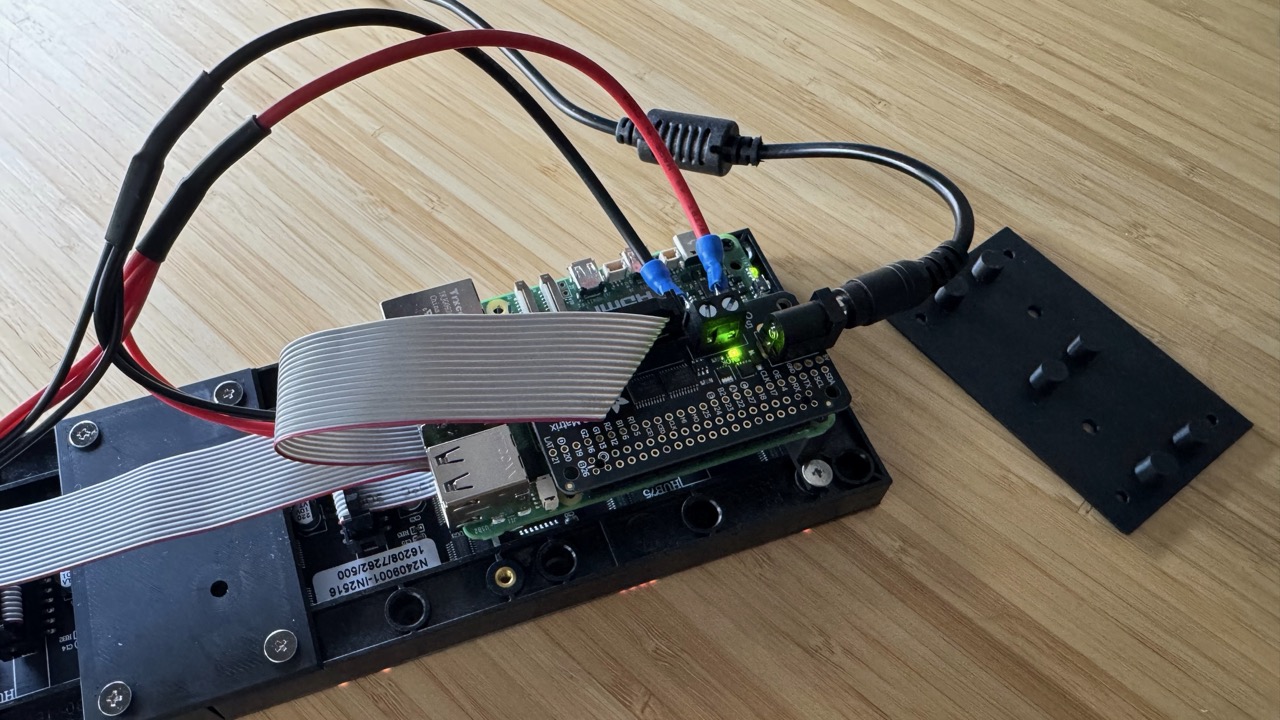
Assembly
The build itself is very simple:
- Raspberry Pi (5 or Zero 2)
- Adafruit RGB Matrix Bonnet
- 2x 64x32 HUB75 LED panels
The main challenge was joining the two LED units to form a single, seamless panel. I designed a simple 3D-printed bracket. The model is included in the GitHub project, along with a riser to attach the Raspberry Pi Zero 2 to the back of the panel. Measurements may vary by manufacturer (I sourced mine here).
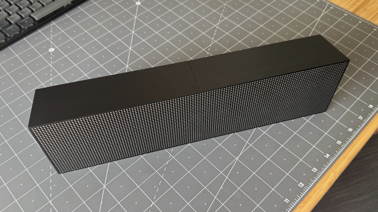
I eventually designed a case to fully enclose the electronics. This had to be printed in two pieces due to the size, but it screws into the LED panels and feels solid.
Conclusion
This was a great weekend project, and a bit of a rollercoaster: getting the CLI bridge working, almost writing the project off over the font, chasing down the flicker, and finally seeing the finished result. 🤩